One SCADA for the whole treatment train, dosing that follows the water, and reports the operating authority can rely on.
The treatment train we automate
PLC + SCADAsequencing, dosing control, filter backwash, alarms, trends, quality and energy reports, remote access
IntakeScreens, raw water pumpsFT, LT
AerationCascade aerator
Flash mixerCoagulant dosingpH, FT
ClariflocculatorFlocculation, settlingTurbidity
Rapid sand filtersAutomatic backwashΔP, Turbidity
ChlorinationResidual Cl₂ trimResidual Cl₂
Clear water reservoirLevel controlLT
DistributionPumps, VFDsFT, PT, kWh
How we automate it, stage by stage (Naidupet 10 MLD WTP as the example)
1
Intake
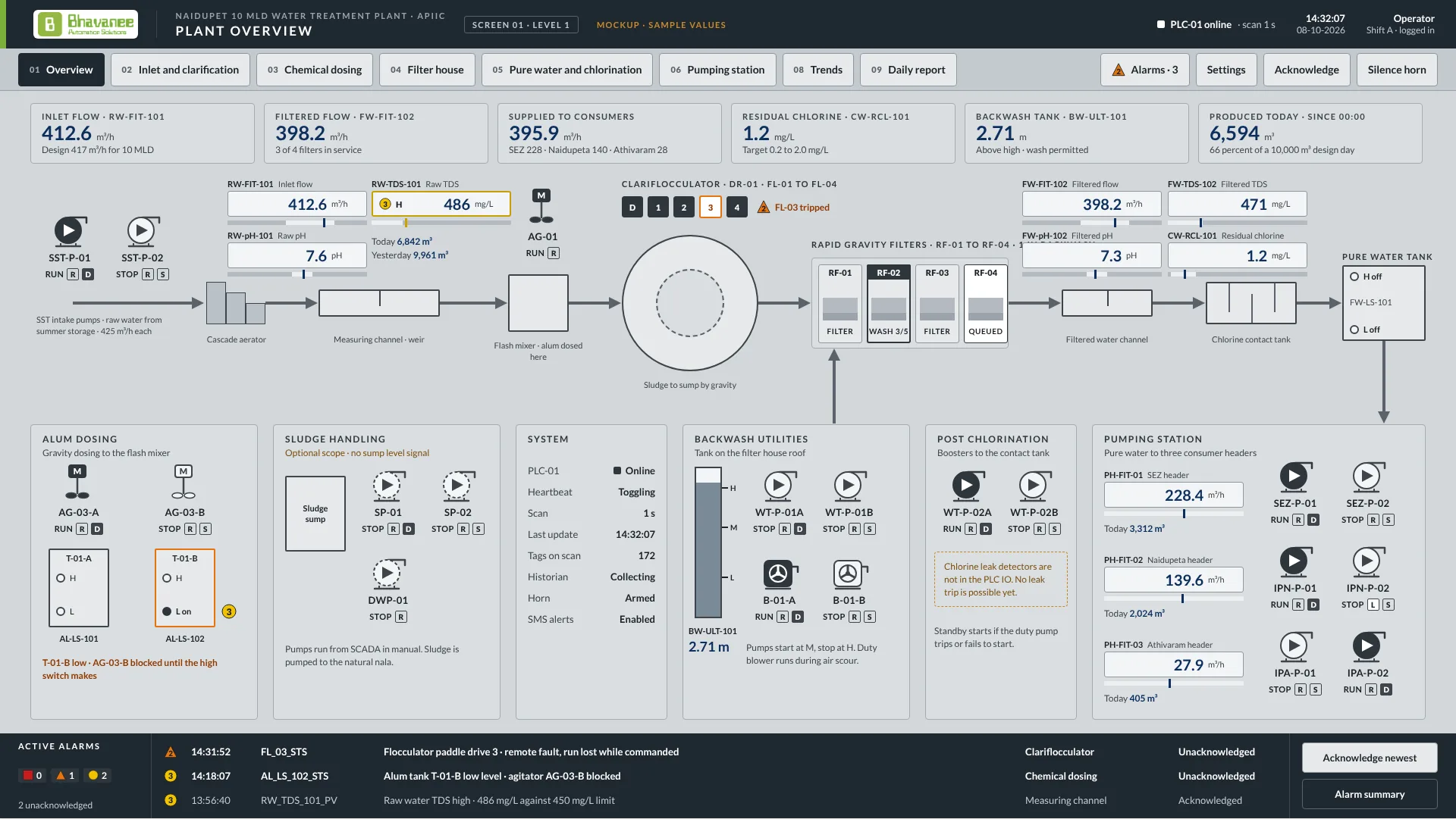
Intake pumps SST-P-01 and SST-P-02 lift raw water from the summer storage tank over a cascade aerator into a measuring channel with a weir.
We automate:Duty and standby selection, run hours per pump, dry-run protection, and raw water flow, pH and TDS (RW-FIT-101, RW-pH-101, RW-TDS-101) with high and low alarms.
2
Dosing and mixing
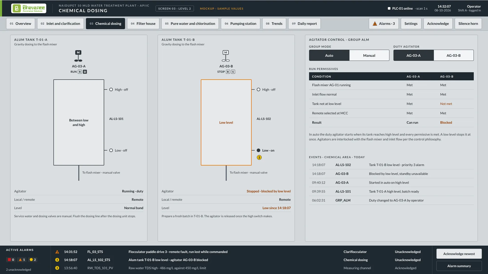
Alum solution from tank T-01-A or T-01-B, each with its own agitator, flows by gravity into flash mixer AG-01, which spreads it through the raw water.
We automate:Dosing paced to inlet flow and trimmed to turbidity and pH, tank level interlocks from the AL-LS switches, and agitators blocked when a tank is low or inlet flow is lost.
3
Clarification
Paddles FL-01 to FL-04 stir the dosed water gently so floc forms in the centre zone, the floc settles in the outer zone, and the bridge DR-01 scrapes sludge to a sump.
We automate:Paddle and bridge drive supervision with run feedback and trip alarms, desludging timers, and sludge pumps SP-01 and SP-02 sent to the nala.
4
Filtration
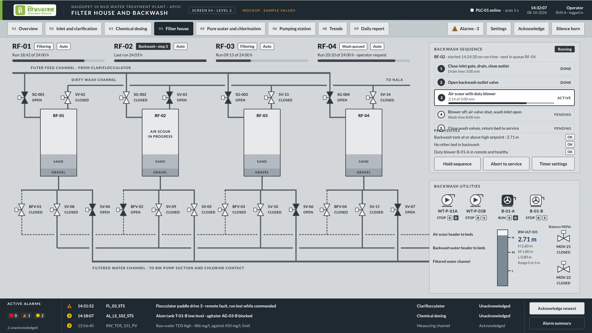
Four rapid gravity filters, RF-01 to RF-04, pass the settled water down through sand and gravel. A dirty bed is washed with air and then water from the roof tank.
We automate:A wash requested on head loss or run time, the 5-step backwash sequence with air scour, one bed at a time, roof tank filling by WT-P-01A/B, and travel alarms on all 22 MOVs.
5
Disinfection
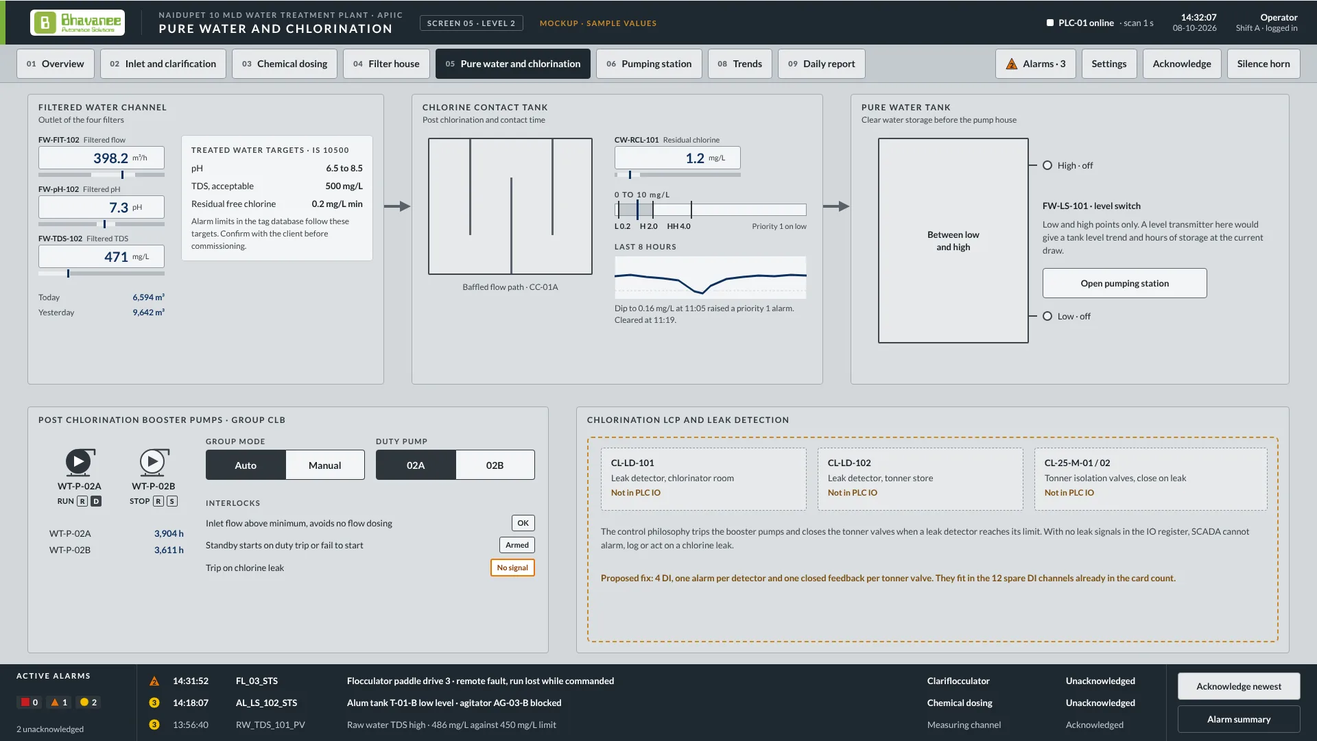
Filtered water is chlorinated and held in a baffled contact tank long enough for the chlorine to act before it goes to storage.
We automate:Residual chlorine trim from CW-RCL-101, filtered flow, pH and TDS (FW-FIT-102, FW-pH-102, FW-TDS-102), with IS 10500 limits set as the alarm limits.
6
Storage and supply
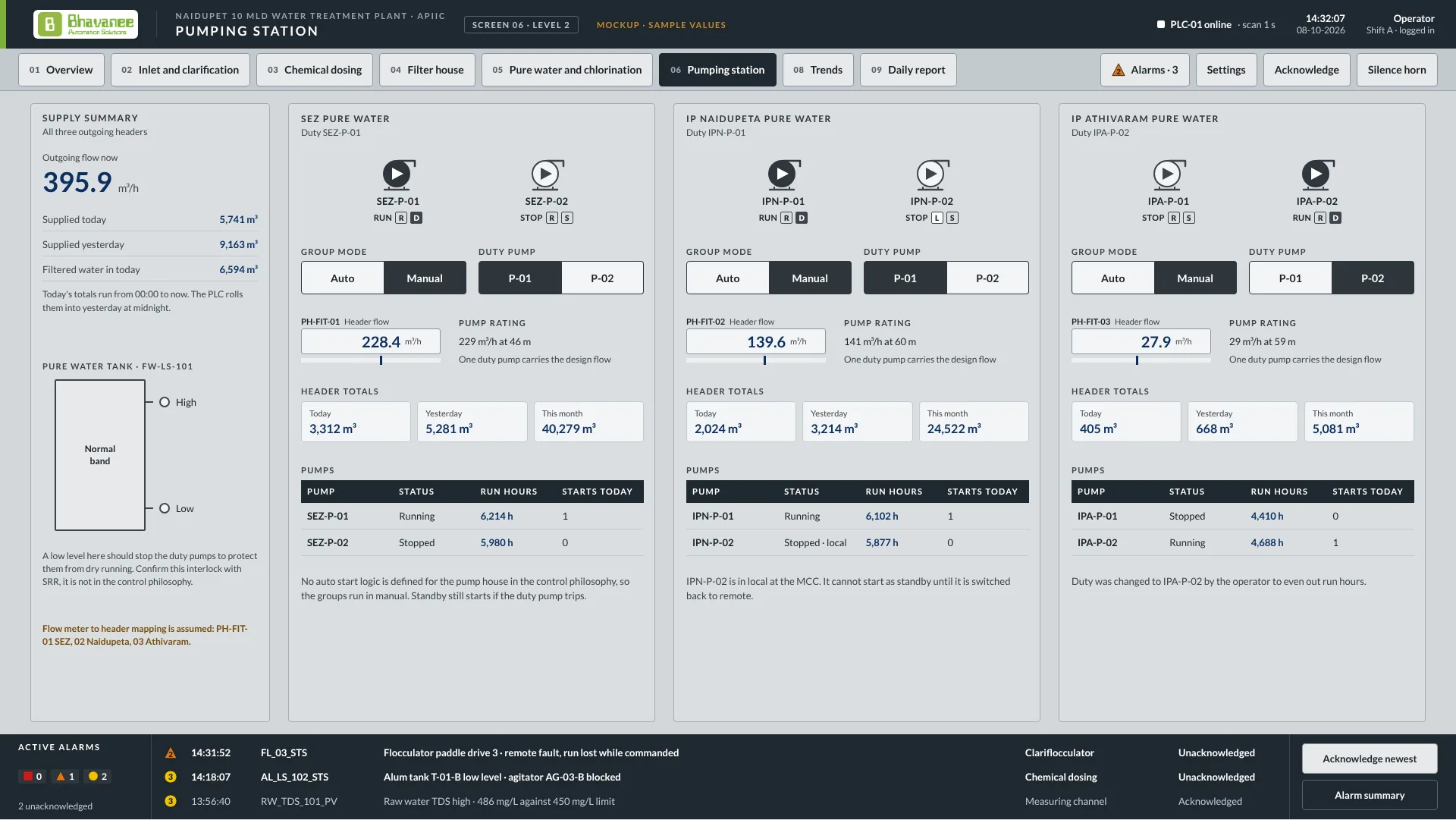
Treated water collects in the pure water tank, and three pump pairs deliver it into the SEZ, Naidupeta and Athivaram headers, each with its own flow meter.
We automate:Duty rotation per header, daily and monthly header totals from PH-FIT-01 to 03, and dry-run protection for every pump from the FW-LS-101 tank level.
7
Control room
PLC-01 and an iFIX SCADA station run the whole plant from one room, with remote overhead tanks and pump houses linked by RTU over 4G.
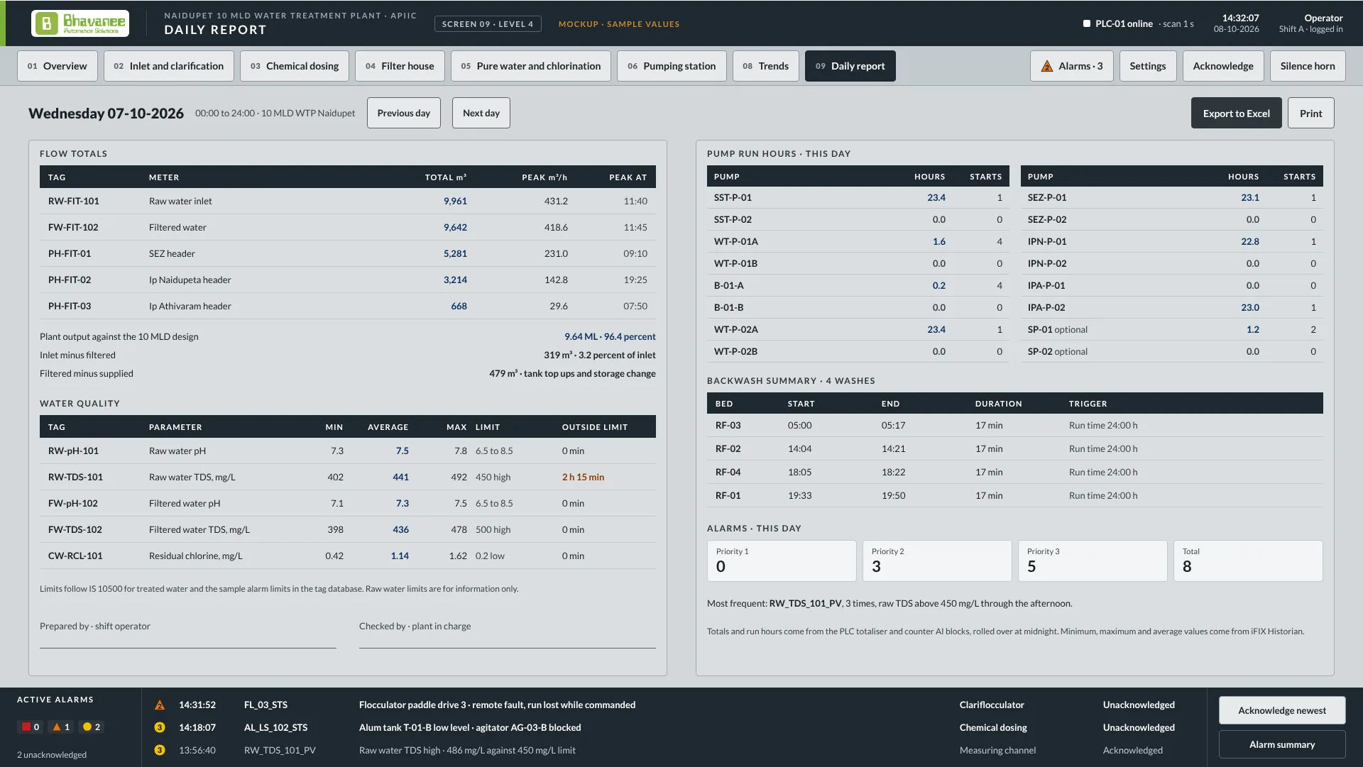
We automate:Alarms with acknowledgement, trends kept in the historian, the daily report of volume, quality and energy, and status from the remote sites.
How a filter backwash runs
1Wash requestedRun time or head loss requests a wash and the bed is queued.
2Bed drainedInlet gate closes, the bed drains, then the outlet closes.
3Air scourBackwash outlet opens and the duty blower air-scours the bed for the set minutes.
4Water washBlower off, air valve shut, wash water from the roof tank for the set minutes.
5Back in serviceWash valves close, the bed returns to service, the run timer resets and the event is logged.
What we deliver
A water treatment plant is a chain of dependent stages. If dosing lags the raw water, the clarifier carries floc to the filters; if filters are not backwashed in time, turbidity breaks through to the reservoir. Our automation ties the stages together so the plant makes consistent water with fewer manual interventions.
Control scope
Raw water intake: pump sequencing and duty rotation, sump level control, VFD speed control, dry run and overload protection.
Chemical dosing: alum or PAC dosing paced to flow and trimmed to turbidity; lime or pH correction; chlorinator control against residual chlorine.
Clarification: clariflocculator drive monitoring, sludge valve timing and desludging sequences.
Filtration: bed level and head loss monitoring, automatic backwash with air scour and wash water sequencing, filter to waste.
Storage and pumping: clear water reservoir level, treated water pump sets, pressure and flow to the network.
Utilities: energy meters on every major drive, DG and power status, chemical stock levels.
Monitoring and reporting
Trends of every flow, level and quality parameter, logged operator actions and alarms, and shift, daily and monthly reports for volume treated, quality, chemical consumption and energy per million litres. Data can be published to a central dashboard so engineers see the plant without travelling to it.
Distribution and remote assets
Overhead service reservoirs, ground level sumps and booster stations connect through RTUs or industrial 4G routers, so tank levels and pump status across the scheme appear on the same SCADA.
Current water work
Our water references include the Naidupet water treatment plant, delivered for SRR Projects inside a government water supply EPC package.
Plant overview, Naidupet 10 MLD WTP (screen design)Filter house and backwash sequenceChemical dosing and interlocksPure water and chlorinationPumping station, three supply headersDaily report for the operating authority
For project heads and buyers
The plant adjusts its own dosing as the raw water changes, washes its own filters when they clog, and prints the daily quality report the water board asks for.
Why it matters
A WTP that depends on operators adjusting dosing by hand produces variable water and a weak quality record. Tender specifications now require SCADA with reporting.
What you receive
PLC panels and SCADA for the whole train
Analyzer-based dosing and automatic backwash
Remote monitoring of distribution assets
Daily, monthly and annual reports, operator training, AMC
Helpful to have
Process flow diagram and capacity (MLD)
Instrument list or tender instrumentation schedule
Remote reservoirs and pump houses to connect
Typical duration
Three to six months depending on plant size, aligned to the civil and mechanical schedule.
How a project runs
Scope callWe go through your P&ID, I/O list or tender clause and agree what the control system has to do.
Technical offerA control philosophy, architecture drawing, bill of materials and price. No surprises later.
Engineering and buildDrawings for approval, PLC logic and SCADA screens built, panels assembled and FAT tested with you present.
CommissioningInstallation supervision, loop checks, start-up and operator training on your site.
SupportDocumentation handover and an annual maintenance contract with a named engineer.
What to send us for a quote
Attach these to your enquiry. The three marked essential are enough for us to start a budget.
Process flow diagram and plant capacity in MLDEssential
They give us the treatment train and the number of filters, pumps and dosing points.
Instrument list or the tender's instrumentation scheduleEssential
It sets the I/O count, which drives panels and price.
Tender clauses for SCADA, reporting and communicationEssential
We quote to what the authority will actually inspect.
Raw water quality range through the year
Analyzer-based dosing has to cover your worst turbidity and pH, not the average.
Chemical dosing details: chemicals, pump type and control method
A stroke-adjusted pump and a VFD pump are controlled differently.
Pump, motor starter and VFD schedule with makes and comms ports
Drives with Modbus or similar ports cut wiring and give us status and fault data.
Remote sites: reservoirs, pump houses and boosters, with location
Count and distance decide the telemetry hardware and network choice.
Reporting formats the authority or operator expects
We build daily, monthly and annual reports to your format from day one.
Civil and mechanical programme
Our site work follows yours, so we need to know when areas will be ready.
Do not have all of it? Send what you have; we work from a site visit for the rest.
What drives cost and schedule
Plant capacity and number of units
More filters, clarifiers and pumps mean more I/O, logic and screens.
Number of online analyzers
Each analyzer-based control loop adds wiring, tuning and commissioning time.
Remote sites and telemetry
Each reservoir or pump house adds a remote panel and a communication link to commission.
Reporting requirements
Custom formats and report approvals add configuration and review cycles.
Civil and mechanical schedule
Our site work cannot finish before your civil and mechanical work does.
Drive and energy integration
Drives with communication ports cost more up front but cut wiring and give energy data.
Typical timeline
Scope and process review1 to 2 weeksProcess, instruments, remote sites and reports agreed.
Drawings and approval2 to 4 weeksPanel, loop and SCADA screen drawings approved.
Panel build and software5 to 8 weeksPanels built, logic and SCADA written to the process.
FAT1 to 2 weeksWhole train simulated and tested at our works.
Site installation3 to 6 weeksFollows your civil and mechanical schedule.
Commissioning and training2 to 3 weeksDosing tuned on live water, reports checked, operators trained.
Overall: Three to six months depending on plant size, aligned to the civil and mechanical schedule.
Budget
Every plant is different, so we price from the I/O list and scope rather than a rate card. Send the documents above and you will have a budget figure within a week, and a fixed price after the scope call.
Automation and SCADA for the treatment plant in SRR Projects' government water supply EPC package.
PLC and SCADA across the treatment train: intake pumps, chemical dosing trimmed against online analyzers, clarifier and filter sequencing with automatic backwash, chlorination and clear water reservoir control, with daily quality and energy reports.
What does a SCADA system do in a water treatment plant?
It monitors and controls every stage from one operator station: raw water pumps, chemical dosing, clarifier drives, filter beds, chlorination and reservoir levels. It raises alarms when quality or equipment drifts, keeps trends, and produces the daily quality and flow reports the operating authority asks for.
Can the SCADA control chemical dosing automatically?
Yes. Dosing pumps are driven in proportion to raw water flow and trimmed against online analyzers, so coagulant and chlorine follow the actual water quality.
Can a WTP be monitored remotely?
Yes. Plant data can be published to a central server or web dashboard over a secure link, and distributed assets report in through RTUs or 4G routers.
Do you work as a sub-vendor to EPC contractors?
Yes. We supply the complete instrumentation, PLC and SCADA package to EPC contractors on municipal and rural water supply projects, from tender stage sizing to commissioning and handover.
Planning a plant, terminal, WTP or substation?
Tell us what you are planning, even if the details are still rough. We reply with a technical approach and an offer.