Bhavanee Automation Solutions
Industry

Water and wastewater automation

Water treatment plants, water supply schemes, reservoirs and pump houses under one SCADA, delivered inside EPC packages for government water supply schemes.

How a water treatment plant runs

Raw water is pumped from the source, aerated, dosed with coagulant and flash mixed, settled in a clariflocculator, filtered, chlorinated and stored in a clear water reservoir before distribution. Each stage depends on the one before it. Our SCADA ties them together and gives the operating authority the quality and energy records it needs.

PLC + SCADA sequencing, dosing control, filter backwash, alarms, trends, quality and energy reports, remote access
IntakeScreens, raw water pumpsFT, LT
AerationCascade aerator
Flash mixerCoagulant dosingpH, FT
ClariflocculatorFlocculation, settlingTurbidity
Rapid sand filtersAutomatic backwashΔP, Turbidity
ChlorinationResidual Cl₂ trimResidual Cl₂
Clear water reservoirLevel controlLT
DistributionPumps, VFDsFT, PT, kWh

How we automate a water treatment plant

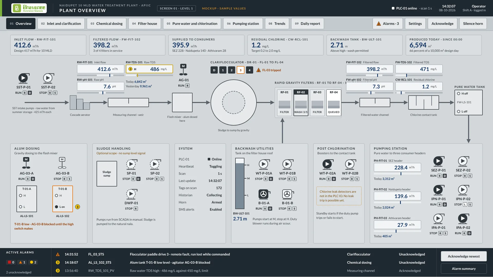
The Naidupet 10 MLD plant as an example: follow the numbers from the summer storage tank to the three supply headers. The control room at the top sees every stage, and the cards say what the PLC and SCADA do at each one.

Water treatment plant process schematicNaidupet 10 MLD water treatment plant. Intake pumps SST-P-01 and SST-P-02 lift raw water from the summer storage tank over a cascade aerator into a measuring channel with flow, pH and TDS measurement. Alum from tanks T-01-A and T-01-B is gravity dosed into flash mixer AG-01. The clariflocculator with paddles FL-01 to FL-04 and bridge drive DR-01 settles the floc, and sludge goes to a sump pumped to the nala by SP-01 and SP-02. Four rapid gravity filters RF-01 to RF-04 are washed with air from blowers B-01-A and B-01-B and water from the roof backwash tank BW-ULT-101, filled by WT-P-01A and WT-P-01B. Filtered water is chlorinated in a contact tank with residual analyser CW-RCL-101, stored in the pure water tank and pumped to the SEZ, Naidupeta and Athivaram headers, each metered. PLC-01 and an iFIX SCADA in the control room supervise every stage, link to remote OHSRs and pump houses and produce the daily report.7Control roomPLC-01 + iFIX SCADARTU / 4G telemetryRemote OHSRs andpump housesHistorian and daily reportReports: daily volume,quality, energy1IntakeSSTSummerstorage tankSST-P-01SST-P-02CascadeaeratorFIT101pH101TDS101Measuring channelRW-FIT/pH/TDS-1012DosingMT-01-AAL-LSMT-01-BAL-LSMFlash mixerAG-013ClarificationMDR-01FL-01..04SettlingClariflocculatorSludge sumpSP-01/02to nala4FiltrationBW-ULT-101Roof tankFilter feed channel22 MOVs sequenced by the PLCDirty washto nalaRF-01RF-02RF-03RF-04Wash waterAir scourFiltered water channelB-01-A/BWT-P-01A/BFIT102pH102TDS102Filtered waterFW-FIT/pH/TDS-102Cl₂RCL101CW-RCL-1015DisinfectionChlorine contact tankFW-LS-101Pure water tankSEZ-P-01/02FIT01PH-FIT-01SEZIPN-P-01/02FIT02PH-FIT-02NaidupetaIPA-P-01/02FIT03PH-FIT-03AthivaramTo consumers6Storage and supplyRaw / filtered waterChemical dosingSludge, dirty washControl signalMotor operated valveAnalyser / meter
  1. Intake

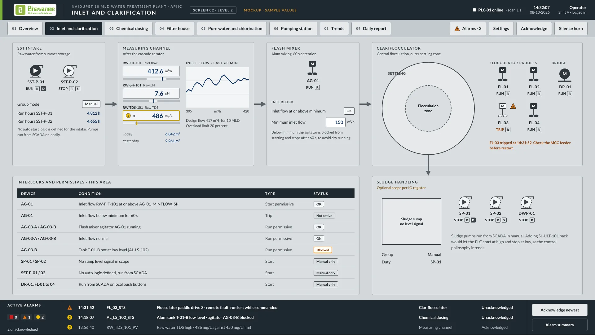
    Intake pumps SST-P-01 and SST-P-02 lift raw water from the summer storage tank over a cascade aerator into a measuring channel with a weir.

    We automate:Duty and standby selection, run hours per pump, dry-run protection, and raw water flow, pH and TDS (RW-FIT-101, RW-pH-101, RW-TDS-101) with high and low alarms.

  2. Dosing and mixing

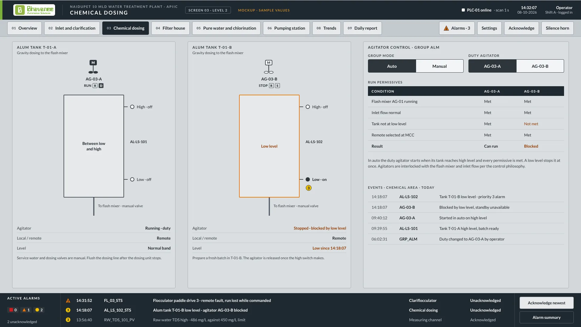
    Alum solution from tank T-01-A or T-01-B, each with its own agitator, flows by gravity into flash mixer AG-01, which spreads it through the raw water.

    We automate:Dosing paced to inlet flow and trimmed to turbidity and pH, tank level interlocks from the AL-LS switches, and agitators blocked when a tank is low or inlet flow is lost.

  3. Clarification

    Paddles FL-01 to FL-04 stir the dosed water gently so floc forms in the centre zone, the floc settles in the outer zone, and the bridge DR-01 scrapes sludge to a sump.

    We automate:Paddle and bridge drive supervision with run feedback and trip alarms, desludging timers, and sludge pumps SP-01 and SP-02 sent to the nala.

  4. Filtration

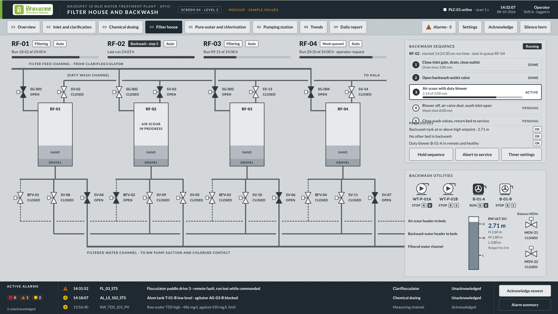
    Four rapid gravity filters, RF-01 to RF-04, pass the settled water down through sand and gravel. A dirty bed is washed with air and then water from the roof tank.

    We automate:A wash requested on head loss or run time, the 5-step backwash sequence with air scour, one bed at a time, roof tank filling by WT-P-01A/B, and travel alarms on all 22 MOVs.

  5. Disinfection

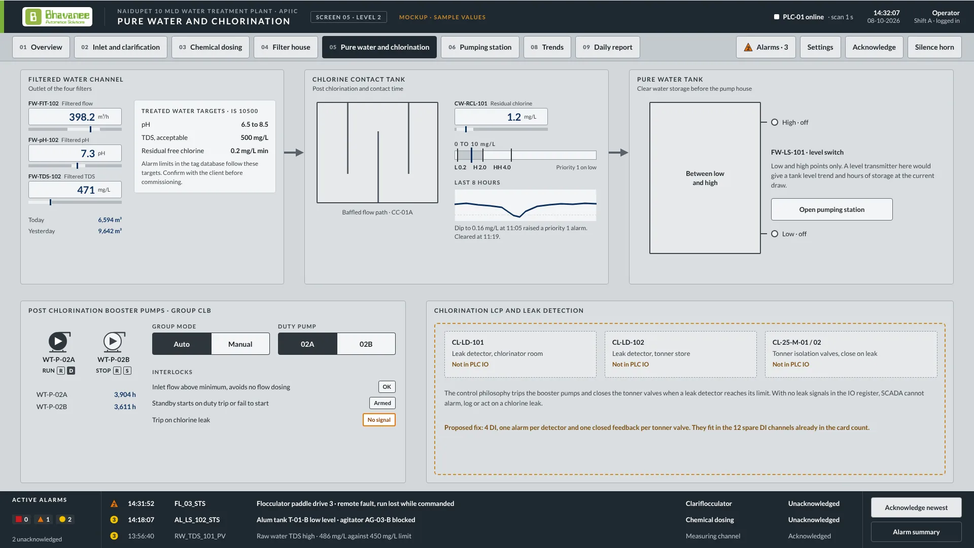
    Filtered water is chlorinated and held in a baffled contact tank long enough for the chlorine to act before it goes to storage.

    We automate:Residual chlorine trim from CW-RCL-101, filtered flow, pH and TDS (FW-FIT-102, FW-pH-102, FW-TDS-102), with IS 10500 limits set as the alarm limits.

  6. Storage and supply

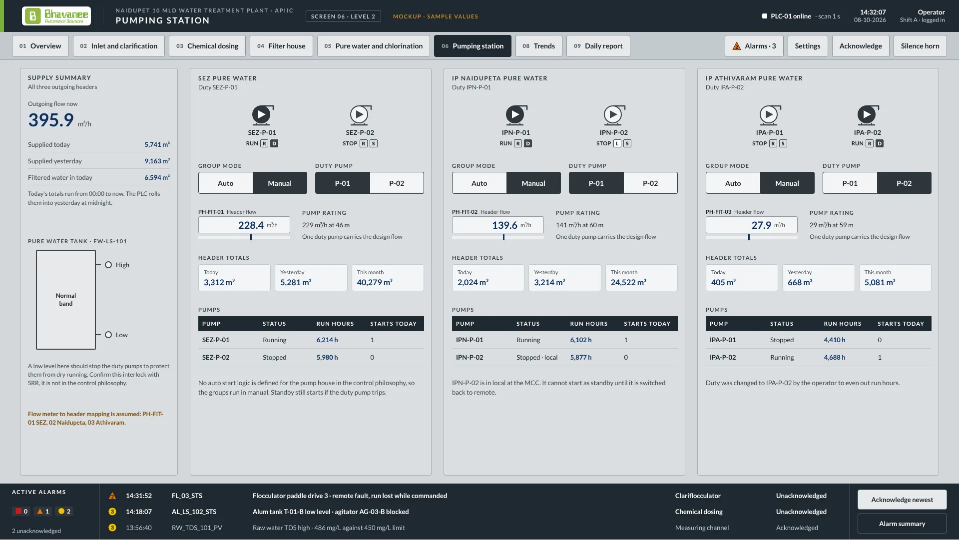
    Treated water collects in the pure water tank, and three pump pairs deliver it into the SEZ, Naidupeta and Athivaram headers, each with its own flow meter.

    We automate:Duty rotation per header, daily and monthly header totals from PH-FIT-01 to 03, and dry-run protection for every pump from the FW-LS-101 tank level.

  7. Control room

    PLC-01 and an iFIX SCADA station run the whole plant from one room, with remote overhead tanks and pump houses linked by RTU over 4G.

    We automate:Alarms with acknowledgement, trends kept in the historian, the daily report of volume, quality and energy, and status from the remote sites.

How a filter backwash runs

  1. Wash requestedRun time or head loss requests a wash and the bed is queued.
  2. Bed drainedInlet gate closes, the bed drains, then the outlet closes.
  3. Air scourBackwash outlet opens and the duty blower air-scours the bed for the set minutes.
  4. Water washBlower off, air valve shut, wash water from the roof tank for the set minutes.
  5. Back in serviceWash valves close, the bed returns to service, the run timer resets and the event is logged.

What the operator sees

The screens we designed for the Naidupet plant: one overview, one screen per area, alarms, trends and the daily report.

Screen designs for the Naidupet 10 MLD WTP (SRR Projects, for APIIC), shown with sample values. Click a screen to enlarge.

What we deliver in water and wastewater

Projects and case studies

SRR Projects, Naidupet, Andhra Pradesh

Naidupet water treatment plant automation

Automation and SCADA for the treatment plant in SRR Projects' government water supply EPC package.

PLC and SCADA across the treatment train: intake pumps, chemical dosing trimmed against online analyzers, clarifier and filter sequencing with automatic backwash, chlorination and clear water reservoir control, with daily quality and energy reports.

  • WTP
  • EPC package
  • Analyzers

Read the case study

Common questions

Do you work as a sub-vendor to EPC contractors?

Yes. We supply the complete instrumentation, PLC and SCADA package to EPC contractors on municipal and rural water supply projects, from tender stage sizing to commissioning and handover. The Naidupet WTP for SRR Projects is a current example.

Can reservoirs and pump houses across a scheme be monitored?

Yes. Remote sites report through RTUs or industrial 4G routers so tank levels and pump status appear on the same SCADA as the treatment plant.

Planning a plant, terminal, WTP or substation?

Tell us what you are planning, even if the details are still rough. We reply with a technical approach and an offer.

Discuss a project